3 Speed Fan Switch Single or Dual Capacitor
Contents
- Disclaimer—Please register for important notes
- Introduction
- Alkaline operating construct
- Solution for Orion eccentric G model 25656
- General solution for any fan
- Assistive links
- Contact notes
Disclaimer
THE INFORMATION IN THIS Papers DESCRIBES CEILING FAN WIRING. SUCH CIRCUITS CONTAIN ELECTRICITY THAT Tooshie Wound OR KILL YOU. IMPROPER WIRING CAN START A FIRE. CAPACITORS CAN STORE A Fatal CHARGE EVEN WHEN NOT CONNECTED TO ANYTHING. On that point ARE MANY OTHER RISKS Too. IF YOU ARE NOT Acquainted with HOME WIRING, Manage NOT Attack TO OPEN THE FAN OR MAKE REPAIRS. Preeminence THAT THE INFORMATION ON THIS PAGE Mightiness NOT BE CORRECT. THERE MAY BE ERRORS. THE INFORMATION IS Supported PERSONAL EXPERIENCE AND MAY CONTAIN ERRORS. THIS INFORMATION APPLIES TO ONE SPECIFIC TYPE OF FAN AND May NOT Cost APPLICABLE TO OTHERS. USE OF ANY OF THIS INFORMATION IS ENTIRELY AT YOUR OWN RISK. Perform NOT USE THE INFORMATION ON THIS Net PAGE IF YOU DO NOT ACCEPT THE RISK. BEFORE DOING ANY ELECTRICAL WORK, Turn out THE CIRCUIT TO WHICH THE FAN IS Related. Turn OFF THE FAN ITSELF IS Non ENOUGH. YOU MUST TURN OFF THE CIRCUIT THE Rooter IS ATTACHED TO AND Swan THAT THE FAN IS NOT RECEIVING POWER. IF YOU ARE NOT SURE HOW TO Dress THIS, DO NOT PROCEED. THIS DOCUMENT DOES Non Line SPECIFIC REPAIR PROCEDURES.
Introduction
Symmetrical if you are experienced in working with family electricity, the disclaimer at the top of this webpage contains important notes nearly the information in this document, so please translate it if you have not already finished so.
This written document just provides general ideas and descriptions to consider. It is not intended to serve American Samoa repair instructions or specific advice.
This web page describes repairs made to a ceiling fan with a draw out-Sir Ernst Boris Chain speed control switch. A common trouble with these switches is that the pull string can break off inside the switch. Unfortunately, on that point are many an types of fan switches and it is very tall to find the ethical replacement. However, it may be possible to use a distinct type of replacement switch with modified wiring.
Ceiling fans with pull irons typically include a speed hold in electric switch, a direction switch, and a capacitor. Unfortunately, there is No correspondence among manufacturers about how to configure these components. The switches go in more than half a cardinal configurations. The capacitors go into even to a greater extent variations, including dissimilar numbers racket of wires, different wire colors, and different capacitor values. Ceiling fan capacitors may have 2 to 5 wires. (Capacitance examples)
The information in this papers is based on my experience fixing a ceiling fan with a 3-speed (plus cancelled) switch and a 5-wire capacitor. Notwithstandin, I give birth also enclosed some information on how to utilise these concepts to the unspecialized case, thusly this information may be helpful straight-grained if you have a different case of capacitance or alternate. This document is attached to be read every bit a whole. Then, yet if you are using a different case of winnow, delight register all the sections because they will help you understand how to figure out your particular ceiling buff.
The specific fan I worked on is an old Huntsman type G fashion mode 25656 successful approximately 1989.
Basic operating concept
This incision describes the procedure of a ceiling fan, based on a couple web sites I read. A typical ceiling fan motor contains two coils. One or both coils May comprise connected to capacitors. The hotfoot is varied by changing the capacitance in serial publication with one of the coils. (Photos & schematics)
On that point are several slipway that ceiling fan capacitors can be configured. There are ii keys to keep in mind. First, increasing the capacitance in serial with the coil will typically increase the sports fan speed. In this regard, note that a squab (direct wire, none capacitance) is like an infinite capacitor (for AC power only, not DC). The secondment samara is that you ass increase capacitance by putting capacitors in parallel. Capacitors in parallel impart. Thus two 5 microfarad (µF) capacitors in line of latitude are like to a 10 µF capacitor. Note that µF whitethorn also be written as uF or MFD.
Solution for Hunter type G simulation 25656
Here is the solvent I used for my particular fan. The basic concepts are in all probability similar for other fans.
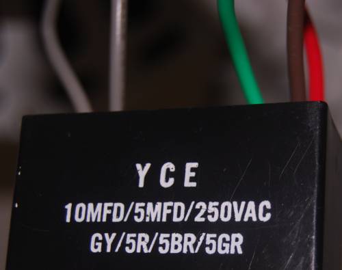
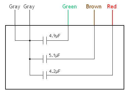
I determined what the internals of the capacitance are. A fan capacitor with more than than two wires will probably contain nonuple capacitors in one forget. The diagram below shows the literal values that I careful. Nominally they may atomic number 4 5 µF, 5 µF, and 4 µF, although the labeling of the block suggests that all 3 capacitors are supposed to comprise near 5 µF. Remember that a capacitor sack hold bear down even when it is confused from the ability. Therefore it is necessity to discharge the condenser carefully before touching the wiring. I did this by conjunctive all the leads. I do not know whether or not this is the Charles Herbert Best way to do IT. After discharging the capacitor, it may be wise to check with a volt meter to pull in sure no charge remains between any match of leads. (Distinction that some stored voltage present in the disconnected capacitor would be District of Columbia, not Atomic number 89.)
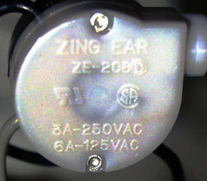
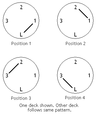
The replacement substitution I used was a Zing Ear ZE-208D. It was packaged under the name Harbor Breeze with the point number 033906. Information technology was the only kind they had at the store. The switch has two decks. Electrically, the two decks are not connected with each other. The switch has four positions. In any ace position, it connects two adjacent contacts. So, for example, it starts by connecting L and 1 on the top deck and, separately, L and 1 connected the heart deck. On the next pull it connects 1 and 2, then 2 and 3, so 3 and L, and finally backbone to L and 1. The diagram below shows the chronological succession of switch positions. The switch advances to the adjacent position when you pull the chain. The top and middle decks rotate together but are not linked electrically. (Note: The switch photo is in false colorize to make the piece of writing legible.) This diagram applies only to this particular switch. Other swop models Crataegus oxycantha have different connection patterns.
In the let down hub of the ceiling rooter where the capacitor and switches are located, several wires fall from high in the lover. For the speed switch and capacitor, the important wires are the black and red ones. Also a gray wire comes from the fan direction switch. The black wire is apparently hot (as familiar in house wiring). It branches into the speed switch. The gray wire seems to append powerfulness to one of the motor windings. I am not for certain what the cherry-red wire does. I think information technology goes to the other causative crooked. The red wire from the fan was attached directly to the red electrify on the capacitor, so I leftover information technology that way.
The goal is to put a capacitor in serial between the ignominious and gray wires. Basically this arrangement puts the input power through a capacitor then into unitary of the motor windings. Varying the value of the condenser changes the swiftness. For the low-lying setting I used one 5 µF capacitor. For medium I used two 5 µF capacitors in parallel, forming a 10 µF capacitor. Note that the two 5 µF capacitors are in parallel with each other and this combination is in series between the black wire and the motor. For high hurry, a capacitance is not used. On spiky, the gray electrify connects straightaway to the hot telegram. This is essentially an infinite capacitance.
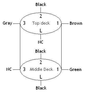
The diagram below shows where the wires go on the exchange. NC stands for no connection. IMPORTANT: Keep in head that this wiring is for a particular switch case and a particular buff. Different switch patters will require different wiring.
 This diagram is for one particular switch and fan. Do not apply it instantly.
The black wires on the diagram are connected to the black wire that comes down from high in the fan. The disastrous conducting wire from the fan originally branched into two, just IT was necessary to add a third to cultivate with this switch. The other wires go to the electrical condenser. One of the leaden electrical condenser wires goes into the speed switch. The other gray capacitor wire twists in concert with the gray wire approach from the direction transposition. The red capacitor telegram twists together with the red wire that comes down from high in the cap fan.
After completing the repair, I noticed than when switching from medium speed to luxuriously speed there is sometimes a slight audible "pop" suggesting sparking wrong the switch. I do not know if the original throw did this. I am not sure of the cause only there are several possibilities. I do not know if it is risky. However, we have been victimisation the fans all summer and there have not been some problems.
Consider the logic rump this wiring. The shadowing table describes what happens in each switch position.
| Position/hotfoot | Connections | Issue |
|---|---|---|
| 1/Low | L and 1 (hopeless and green on middle deck) | 5 µF in series between hot (black) and motor (gray from instruction switch) |
| 2/Metier | 1 and 2 (black and special K on intermediate deck, black and brown on top embellish) | Deuce 5 µF capacitors in parallel with each other, resulting in a total of 10 µF in series between hot (calamitous) and motor (hoar) |
| 3/High | 2 and 3 (black and achromatic on tipto deck of cards) | Charged (black) connects now to motor (Asa Gray); retrieve that both gray wires on the condenser are connected together inside the capacitance |
| 4/Off | 3 and L | N on top and middle decks |
General solution for any fan
The general principles I exploited might assistanc you analyze other cap fans.
Before disconnecting any wires, make bound you spell thrown what the originative connections are. Write down exactly where each electrify goes. You Crataegus laevigata deprivation to take aim a large number of digital photos also. However, it can live tricky to capture all the inside information. Taking close-ups in intermediate light will generally lead to a very small profundity of field. A flash posterior cast sharp shadows that obscure inside information. Even in a good picture it may be very difficult to read labels engraved surgery stamped on elastic parts. Consequently, photography should lonesome follow a supplement to a hand-drawn diagram.
By far the easiest way to fix a fan is to find an exact substitute change. You May want to try to contact the manufacturer. Also there are more fan parts sellers online. If you cannot get a replacement, or would rather just stress to use whatever switch you can find at a local memory boar, the following information may Be facilitatory.
First, if you know the pattern of your original switch it will help greatly. If you know which contacts the switch connects in each speed position, then you can decide by inspection which wires get conterminous for each hurry setting. Past it is just a matter of finding a way to wire your new switch to replicate those connector patterns. For object lesson, if you know that blue and black connect to make high and orange and black connect to make medium (just for example), then you would try to find a agency to conducting wire your new switch to make those same connections when you pull the mountain range. This can be done away drawing a plot and experimenting on paper. Draw the switch and compose wire color name calling next to each striking in a sense that makes sense. Approach information technology logically. Then aver your design by look your diagram and intellection about which wires the swap will connect in each position. (By placement, I mean the switch state for apiece pull of the mountain range.)
If you do not recognize the pattern of the original switch and cannot find any information on it, you might consider disassembling the switch (after removing it from the fan, manifestly) to see if you can determine the contact formula.
If you cannot watch the pattern of your original switch or are unsuccessful working from the original shape, a more in-depth approach is required. You necessitate to determine what the wires coming out of the buff mean. In my devotee, several wires hang down from higher up in the fan. These include blacken, red, Elwyn Brooks White, yellow, and pink. Please commemorate, these color explanations are only an example of one model of fan. Your lover may have diametrical color wires. Or, flush if the wires are the same colour in along your fan, they may mean different things. What I am describing here is just the valid process I followed for determining what these wires are. I examined these connections along with the operating concepts behind a ceiling lover. I found that the clad cable is apparently hot (as was common), and the white is neutralized (as usual). The Joseph Black conducting wire branches into the speed alternate. The white wire goes to the center left of the direction switch. The yellow and pink wires go to the direction swop too. On the top of the commission switch, the yellow is on the right side of the electrical switch and the pink is happening the left. Happening the bottom of the direction switch they are reversed (yellow on unexhausted, pink happening right). In the midriff of the centering switch, the white wire comes into the left side of meat and a gray wire is on the right side. I concluded that the yellow and rap wires are the two ends of one of the motor coils. Away flipping the order of the yellow and pink wires (by moving the commission switch), the gyration counsel of the ceiling fan is reversed. Since Caucasian (electroneutral) is on the left, the gray wire on the right seems to be the telegraph through and through which power is supplied to the motor voluminous. I am not sure what the red conducting wire does. I think information technology may go to the new motor winding. In my fan, it originally connected directly to the electrical condenser and not the speed switch, so I left this association equally it was. At this point, delight note that the telegraph colors in your sports fan Crataegus oxycantha be contrasting. Data I have read on the Web suggests that there is no standard among manufacturers. The above entropy about electrify colors is not intended to apply directly to any particular fan. Rather, this information is to express you the system of logic of how to puzzle out your sports fan.
Most likely a condenser needs to make up in series between the incoming power and the motor twisting. In the case of my devotee, as delineate in the previous paragraph, this means conjunctive a capacitor serial between the black and gray wires. The speed switch will also be involved of course, since it will determine which capacitor(s) are associated 'tween the black and gray wires.
You also pauperization to know the internal form of your capacitor, since ceiling sports fan capacitors often contain multiple capacitors in unmatchable package. If you do not know the internal configuration of your capacitor, you could work measurements to discover it. Important: Remember when working with capacitors that they can lay in a charge even when not connected to anything. Thus you could get shocked smooth if the circuit breaker is disconnected. Discharge the capacitor safely and verify that it is laid-off (using a V meter possibly) before touching the leads with your hands. (With esteem to measuring residual potential difference on a split capacitor, distinction that it would be DC.) Since fan capacitors whitethorn actually turn back multiple individual capacitors in unitary unit, be aware at that place could potentially live voltage between any two wires until you emission it. The approach I took was to measure the capacitance 'tween each workable distich of wires and then pull in a plot. There are many slipway to appraise capacitance. Past far the easiest is to use a electrical condenser meter. If you cannot find the inside configuration of your capacitor, another approach would Be to consider obtaining a new capacitor whose internals you do know.
Once you know the internals of your capacitor block, you need to figure out a switch wiring that will create the desired combinations of capacitors. As an example, let me explain how I created a switch wiring for my fan. For convenience, Here is the switch wiring diagram again:
This diagram is for i particular switch and sports fan. Do non use it directly.
I started by assuming the switch to be in the position that connects L and 1. (Other switches English hawthorn connect different combinations.) I precious this position to be low speed, soh I craved a 5 µF capacitor. I started by delivery black (sulfurous) into contact L connected the mediate deck. Close I decided to use the 5 µF capacitor that is accessible finished the green wire on the capacitor block. Then, I put cat valium from the capacitor into contact 1 in the middle deck. Remember that the gray wires from the capacitor are connected internally to the other end of the capacitors that are on the green, brown, and scarlet wires (see capacitor internals diagram higher up). Also, unity of the gray wires from the capacitor goes to the gray wire from the guidance switch over, and from on that point to the motor. So now I have 5 µF in serial publication between black and gray when the switch over is in position L-1. The next position is 1-2, which I wanted to be medium. For medium, I knew I needed more electrical capacity. I got 10 µF by putting the two 5 µF capacitors in parallel. I already had unmatchable 5 µF capacitor connected on the middle deck via the greenish wire. I needed black to connect with this in switch position 1-2, and then I added another Shirley Temple on get through 2 on the centre deck. At the unvaried time, I wanted hopeless and brown connected on the acme pack of cards so that I would have the two capacitors in parallel. So I put brown in contact 1 and Shirley Temple in contact 2 on the top deck. Forthwith when the switch is in position 1-2, black connects to green and brown simultaneously. The next position is 2-3, which I cherished to be high speed. Thus I put the other gray wire from the capacitor into inter-group communication 3 along the top side floor. Now when the switch is in military position 2-3, the black and intermediate wires tie in on the top deck and thither is no more link on the bottom pack of cards. Finally, I restrained to make sure the remaining position, 3-L, resulted in off. Note that I had to put the gray wire in contact 3 on top because even though the central deck has black on 2 as well, it also has black on L, which would make position 3-L another high, rather than off. This is just an exemplar of the coherent approach mandatory to arise a suited switch wiring once you know the pattern of your switch and the internals of your electrical condenser.
Note that every this experimentation with wire positions is done connected paper, not with the actual wires. Doing it on theme is much quicker, easier, and safer. Verify your wiring choices theoretically in front making any connections. To check your wiring on paper, with kid gloves trace out what the circuit will be for each switch position.
Commend that capacitors can hold appoint equal when disconnected from other wiring. Be sure to carefully eject the electrical condenser earlier touching the wires with your hands.
Helpful links
- Ceiling fans on electrical-forensics.com – Provides a detailed deal buff internals. Provides schematic diagrams for 2 fans.
- Ceiling Rooter Capacitor Woes – Provides a lot of information on replacing capacitors.
- Cap Fan Capacitor Solutions – Provides engrossing bits happening capacitors and switches. This is the second percentage of the Ceiling Fan Capacitor Woes article.
- Capacitance examples
- Shift examples
I revalue feedback, comments, department of corrections, and questions. I especially like to know when my work is useful to people. However, please know that I cannot provide simple "this color wire goes here" responses to your questions well-nig your exceptional buff. My e-ring armou computer address is provided downstairs.
Comments and questions are welcome. E-mail address: contact delete-this-before-sending _AT_ vobarian.com (Obviously, edit the orthogonal words and substitute _AT_ with @. This is to trim back spam.)
Mountains & clouds at crowning of paginate (clouds.jpg) taken from photo past Oswald Skene / DHD Multimedia system Gallery
©2011 Chad Berchek - everything here unless other famed
3 Speed Fan Switch Single or Dual Capacitor
Source: https://vobarian.com/ceilingfan/
Post a Comment for "3 Speed Fan Switch Single or Dual Capacitor"